
The computational mesh, defined by cell size, is the foundation of any FDS fire simulation. Smaller cells produce more accurate results, particularly for simulating complex smoke and heat flows, but they require significantly more processing power.
Best practice involves a:
These selections are governed by the characteristic fire diameter (D*) and its ratio to the mesh size (D*/δx), which should meet recommended thresholds:
Fire size is expressed as the peak Heat Release Rate (HRR) and is determined based on factors such as the building’s occupancy type, expected fire load, and the presence or absence of suppression systems.
For example, office buildings and metro stations equipped with sprinklers are typically modelled using fire sizes in the range of 1–2 MW, while shopping malls, warehouses, and metro rolling stock generally require larger design fires in the range of 5–10 MW.
To ensure the robustness of the smoke control strategy, it is essential to conduct sensitivity analyses using higher fire sizes, particularly to account for potential failure scenarios such as sprinkler malfunction or delayed system activation. All proposed fire sizes should be reviewed and confirmed in consultation with key project stakeholders, including fire engineers, MEP consultants, and relevant authorities.
FDS models fire growth using t-squared (t²) fire curves, where the fire’s Heat Release Rate (HRR) increases proportionally to the square of time. The selected growth rate depends on the fire environment and expected ignition behaviour. The growth rate is defined by the coefficient α, with commonly adopted values as follows:
Slow and medium fire growth rates are typically used in low-risk or early-detection environments such as offices and corridors, while fast and ultra-fast rates are reserved for high-risk or fuel-rich areas like storage rooms, retail display zones, or atriums containing combustible materials. The selected growth rate has a direct impact on available evacuation time and the activation of smoke control and suppression systems.
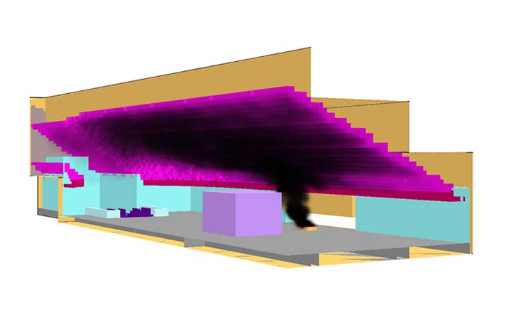
The location of the fire in the model must reflect realistic and high-risk ignition points. Placement should be informed by known ignition sources or areas with high occupant density. For performance-based assessments, additional fire scenarios should be modelled near critical elements such as exits or extraction points to assess the robustness of smoke control and egress systems.
Soot and carbon monoxide (CO) production have significant implications for both visibility and occupant life safety during a fire event. In fire modelling,
These parameters directly influence tenability assessments in evacuation modelling by affecting both the optical density of the smoke layer and the toxicity of the environment, thereby informing the safe egress time and performance of smoke management systems.
FDS allows virtual smoke detectors to be programmed into the model. These simulate detection of smoke or heat and trigger the operation of smoke control systems. Realistic modelling includes a system response delay of 10 to 20 seconds delay for accounting signal transmission and 60 to 120 seconds for mechanical ramp-up time. This approach ensures that simulations replicate expected building system behaviour as defined in MEP specifications.
FDS calculates total heat release by combining convective and radiative components. At least 35% of the HRR should be allocated to radiation unless otherwise supported by testing or manufacturer data. The heat of combustion should be selected based on fuel characteristics and validated references such as safety data sheets or experimental literature.
Visibility is a key metric in fire modelling. FDS uses a visibility factor (C) to relate smoke concentration to visual obscuration. For reflective surfaces, C = 3 is commonly used, while C = 8 applies to illuminated signs. Using C = 3 ensures a conservative assessment of evacuation visibility under smoky conditions.
The HRRPUA defines the energy released per square metre of burning surface and is particularly important for materials with surface flame spread. It should be supported by fire test data or reliable literature, such as CIBSE Guide E or NFPA, ensuring that design assumptions are grounded in empirical performance data.
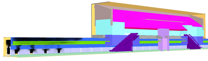
Ambient temperature must reflect realistic environmental conditions. In air-conditioned or mechanically ventilated buildings, a typical range of 20–25°C is applied. This baseline affects smoke buoyancy and ventilation behaviour, making it an important parameter in accurate CFD simulation.
All mechanical ventilation components, such as exhaust fan flow rates, makeup air volumes, and fan activation timings, should be cross-checked against MEP specifications. This ensures consistency between the CFD model and the actual design intent of the ventilation system.
To properly capture fire growth, smoke spread, and system responses, simulation duration should be at least 20 minutes or RSET x FoS, whichever is greater, in accordance with the UAE Fire and Life Safety Code. However, a 30-minute simulation is often preferred, particularly when system activation is delayed or when tenability needs to be assessed over longer periods or when a steady state of smoke layer is not achieved.
At LAVA Consultants, our CFD fire modelling services are built on internationally recognised best practices and tailored to local regulatory requirements. Whether you are designing a metro station, high-rise building, warehouse, or tunnel, our expertise ensures your fire strategy is robust, compliant, and based on sound engineering principles.

© 2025 Lava Consultants. All rights reserved